
Particulate Contamination in RTU Packaging: Standards and Realities
Particle Classifications in Parenterals
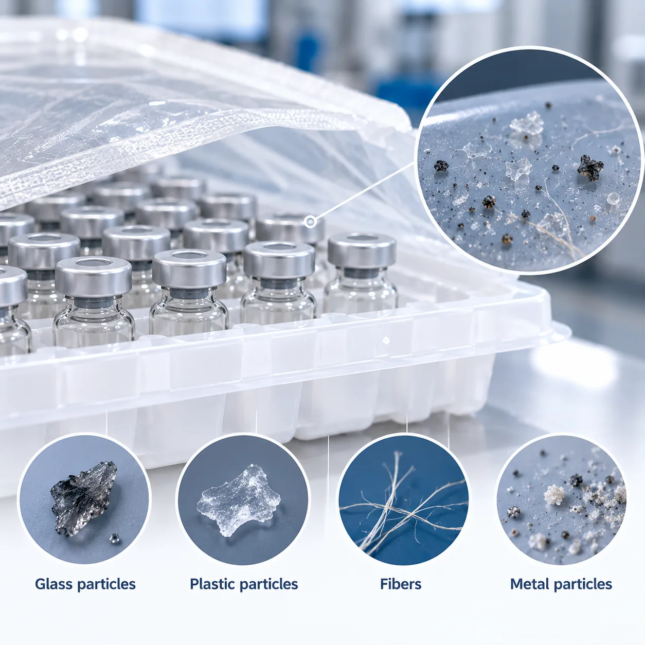
Contaminants inside sterile containers fall into three distinct categories:
- Extrinsic Particles: Foreign matter originating from outside the processing environment. Common examples include cellulose fibers, hair, processing debris, and environmental dust. These present the highest regulatory and patient safety risks.
- Intrinsic Particles: Matter generated from packaging materials, processing equipment, or container-closure assemblies. Key sources include rubber core fragments, glass delamination flakes, silicone oil microdroplets, and nest polymer abradants.
- Inherent Particles: Substances that are a natural part of the drug formulation itself, such as therapeutic protein aggregates or colloidal suspensions.
Visible vs. Sub-Visible Particle Profiles
| Characteristic | Visible Particles | Sub-Visible Particulate Matter |
|---|---|---|
| Size Range | Typically ≥ 100 µm | 2 µm to 100 µm |
| Primary Detection Method | Manual visual inspection / AVI systems | Light obscuration particle count, flow imaging microscopy |
| Clinical Risk | Immediate vessel occlusion, embolic trauma | Capillary blockage, systemic immunogenicity |
| Common Sources | Heavy fiber shedding, large glass chips | Silicone droplets, micro-sheared polymer dust, glass micro-flakes |
Regulatory Limits: USP <788>, USP <787>, and Ph. Eur. 2.9.19
Sterile injectable containers must strictly comply with sub-visible particulate matter limits before release. While USP <788> and Ph. Eur. 2.9.19 set standard injectable limits via light obscuration and microscopic assays, USP <787> addresses therapeutic protein injectables requiring smaller test volumes.
| Pharmacopeial Standard | Test Volume | Particle Threshold: ≥ 10 µm | Particle Threshold: ≥ 25 µm |
|---|---|---|---|
| USP <788> (Small Volume Injectables, ≤ 100 mL) | Standard (≥ 5 mL) | ≤ 6,000 particles / container | ≤ 600 particles / container |
| USP <788> (Large Volume Injectables, > 100 mL) | Standard | ≤ 25 particles / mL | ≤ 3 particles / mL |
| USP <787> (Protein Injections) | Micro-volumes (< 1 mL to 5 mL) | ≤ 6,000 particles / container | ≤ 600 particles / container |
| Ph. Eur. 2.9.19 | Standard | Aligned with USP <788> limits | Aligned with USP <788> limits |
EU GMP Annex 1 Contamination Control Strategy (CCS) Requirements
Under EU GMP Annex 1, particulate contamination in RTU packaging requires a documented, end-to-end Contamination Control Strategy (CCS). Regulatory expectations mandate that:
- Packaging manufacturers and fill-finish facilities actively control particle-generating mechanisms across the entire container lifecycle.
- Particle burden validation covers critical process points: washing, depyrogenation, cleanroom nest loading, and transit handling.
- Critical processing surfaces maintain ISO Class 5 / Grade A cleanliness conditions to prevent static-driven particle deposition before container sealing.
- Container closure integrity (CCI) and sterile barrier performance remain intact without shedding fibers or particulate debris during sterile handling.
Root Causes of Particulate Contamination in RTU Packaging
When we troubleshoot batch rejects on aseptic fill-finish lines, particulate contamination in RTU packaging almost always traces back to mechanical interfaces, material handling, or static dynamics. Identifying the exact mechanism is the only way to safeguard container cleanliness before the filling needle ever drops.
Mechanical Abrasion and Transit Friction
During transit, vibrations cause microscopic shifts between the nested containers and the plastic carrier holes.
Vial-to-Nest Chafing: Micro-motion rubs glass against polypropylene or polyoxymethylene ribs, generating plastic shavings and glass flaking.
Tub Rattle: In poorly secured packaging arrays, vertical shock allows containers to bounce, creating visible contact scuffs.
We engineer our vial nest and tub system for RTU aseptic fill-finish with strict dimensional tolerances to lock each container in place, dampening road vibration and stopping friction-induced shedding.
Sterile Barrier Peeling and Fiber Shedding
Opening the pre-sterilized tub introduces an immediate mechanical shear risk:
Adhesive Rupture: Peeling the breathable Tyvek lid away from the tub flange creates high shear stresses. If the peel seal isn't balanced, adhesive micro-tears leave floating particulate on top of open containers.
Filament Release: Inconsistent peel angles cause fiber tear rather than a clean adhesive release, shedding breathable membrane fragments into the surrounding laminar airflow.
Triboelectric Static Build-Up
Polymer tubs and nests generate massive electrostatic charges during automated conveyor transport and glovebox manipulation.
Surface Charge Accumulation: Typical plastic nests can carry static charges exceeding 5 to 10 kV.
Active Particle Attraction: This charge acts as a magnet, drawing airborne dust, shed cleanroom gowning filaments, and mechanical debris directly toward container openings before filling begins.
Upstream Residues and Silicone Oil Microdroplets
Not every particle entering your batch comes from mechanical contact:
Free Silicone Migration: Excessive or uneven silicone oil applied to stoppers and syringe barrels can aggregate into sub-micron and sub-visible particulate matter when interacting with aqueous formulations.
Washing and Depyrogenation Remnants: Sub-visible inorganic salts or pyrogen residue left from upstream washing lines can bake onto container walls if water-for-injection rinse cycles fall below spec.
Robotic De-Nesting and Gripper Interference
High-speed automated fill-finish cells introduce secondary mechanical contact points:
Gripper Misalignment: Robotic end-of-arm tooling that enters nest openings with slight offset can scrape against container necks, creating visible plastic or metallic fragments.
Clamp Wear: Mechanical gripper pads made of degrading elastomers shed particles straight into open container bores during rapid pick-and-place movements. Employing optimized nested tub and tray aseptic processing solutions helps line operators stabilize nest alignment and eliminate off-center gripper drag.
Analytical Testing for Particulate Contamination in RTU Packaging
Light Obscuration vs. Membrane Microscopy
For routine release and USP 788 compliance, light obscuration particle count testing serves as our first line of defense. However, when working with opaque suspensions or viscous drug matrices, membrane microscopic counting becomes mandatory to resolve optical interference.
| Method | Primary Detection Capability | Key Limitations | Best Application |
|---|---|---|---|
| Light Obscuration (LO) | Rapid sizing & counting (≥10 µm and ≥25 µm) | Cannot distinguish particle composition; misreads bubbles | Clear solutions, rapid batch release audits |
| Membrane Microscopy | Visual identification, color grading, shape analysis | Labor-intensive; subjective operator variance | Confirming extrinsic fiber flakes, metal, or glass fragments |
Flow Imaging Microscopy (MFI)
Standard light obscuration cannot tell the difference between a flexible protein aggregate and a spherical silicone droplet. We deploy Micro-Flow Imaging (MFI) to capture real-time brightfield images of sub-visible particulate matter suspended in the stream.
- Silicone oil microdroplets: Appear with high optical contrast and a circularity index near 1.0.
- Packaging polymer slivers: Display irregular aspect ratios, ragged edges, and lower transparency.
- Proteinaceous matter: Translucent, irregular morphology captured under USP 787 protein injectables protocols.
FTIR and SEM-EDS Chemical Mapping
When foreign particulate matter is detected inside a sterile RTU vial tray kit for biologics and pharmaceutical or within a prefilled syringe nest and tub for safe handling, we apply spectroscopic tools to establish a definitive root cause.
- Fourier Transform Infrared Spectroscopy (FTIR): Identifies organic contaminants. We use micro-FTIR to map signature absorption spectra directly back to Tyvek lid peeling particulate, nest polymers, or elastomeric closure shavings.
- Scanning Electron Microscopy with Energy Dispersive X-ray Spectroscopy (SEM-EDS): Evaluates hard inorganic matter. SEM provides high-resolution surface topography, while EDS delivers elemental composition down to the sub-micron scale, immediately differentiating stainless steel wear particles from glass delamination flakes.
Engineering Controls to Stop Particulate Contamination in RTU Packaging
Precision Nest and Tub Geometry to Stop Glass-to-Glass Contact
Direct contact between containers during transport is a primary driver of sub-visible glass flakes and cosmetic scuffing. When containers rub against one another under transit vibration, the friction generates microscopic glass fragments that breach USP 788 compliance thresholds.
- Individual Pocket Isolation: We engineer custom cavity profiles that lock each container into a dedicated vertical nest slot, maintaining a strict physical clearance between neighboring units.
- Base Suspension: Containers rest suspended above the tub floor, preventing bottom-surface abrasion during pallet handling and shipping.
- Multi-Format Protection: Whether handling vials or configuring pharmaceutical cartridge nest and tub sterile packaging, the nest geometry keeps container walls fully isolated from dynamic friction.
Low-Shedding Sterile Barrier Films and Validated Peel Parameters
Opening sterile barrier lids during automated fill-finish can generate polymeric and cellulosic micro-fibers if the seal adhesive fails or tears unevenly.
- Cohesive Seal Peeling: We deploy low-shedding medical-grade barrier lids engineered for clean adhesive release rather than material delamination.
- Controlled Peel Forces: Sealing parameters are validated within a tight temperature and pressure window to ensure seal integrity while maintaining an easy, smooth peel profile.
- Reduced Fiber Shedding: Minimizing tear-edge friction prevents micro-lint generation when robotic grippers remove the outer lid in sterile barrier zones.
Ionizing Air Blowers and Static Charge Neutralization
Polymer tubs and nests naturally generate triboelectric surface charges during automated de-nesting and conveyance. These electrostatic charges actively pull floating particles toward open container mouths.
- Targeted In-Line Ionization: We utilize high-output ionizing air bars across automated handling bays to flood components with alternating positive and negative ions.
- Charge Decay Optimization: Bringing surface voltage below 100V strips the electrostatic attraction field, preventing airborne dust and shedding fibers from adhering to polymer nests.
- Static-Neutral Robotic Pick Points: Gripper interfaces incorporate conductive grounding to stop static build-up during rapid container transfers.
ISO Class 5 / Grade A Cleanroom Processing and Ultrasonic WFI Washing
The cleanest packaging format starts with rigorous upstream contamination management before components ever reach the sealing station.
- Multi-Stage Ultrasonic Cleaning: Primary containers undergo multi-frequency ultrasonic washing in hot Water for Injection (WFI) to dislodge adhered manufacturing fines and sub-visible residues.
- Depyrogenation and Hot Air Sterilization: Cleaned glass travels directly into continuous hot-air tunnels to ensure depyrogenation while maintaining particulate-free container interiors.
- Grade A Environment Assembly: Nest insertion, tub loading, and sterile barrier placement take place strictly under ISO Class 5 / Grade A unidirectional airflow systems to guarantee pristine ready-to-use primary packaging.
| Engineering Control | Target Particle Type | Operational Impact on Fill-Finish |
|---|---|---|
| Pocketed Nest Architecture | Glass-to-glass abrasion particles | Eliminates transit delamination and visual defects |
| Clean-Peel Barrier Films | Polymeric and Tyvek lid fibers | Reduces particulate fallout during lid removal |
| Static Ionization Bars | Environmental airborne dust | Prevents static-driven particle capture |
| Ultrasonic WFI Washing | Sub-visible manufacturing fines | Ensures baseline compliance with USP 788 limits |
Supplier Manufacturing Controls: The Jiahua Packaging Benchmark
Preventing particulate generation requires tight upstream manufacturing controls rather than relying solely on downstream point-of-use rinsing.
When evaluating options or selecting an RTU supplier for small-batch biologics, our production standards target root-cause particle sources through disciplined engineering:
- Cleanroom-Controlled Upstream Assembly: All thermoforming, injection molding, and nest-and-tub assembly take place within strictly classified ISO cleanroom environments. Automated handling systems eliminate direct operator contact, keeping foreign particulate matter (FPM) away from primary contact zones.
- Anti-Vibration Nest Design: Glass-to-glass contact remains a primary driver of sub-visible glass flakes. Our nest architectures lock each container firmly in place. By damping dynamic transit vibrations, our vial packaging engineered for secure transit eliminates the mechanical chattering and surface micro-abrasion that typically shed particles during transport.
- Anti-Static Polymer Formulations: Friction between plastic tubs and nests naturally generates static charges that pull airborne dust into open containers. We utilize anti-static polymer treatments and in-line ionization fields during packing to neutralize charge buildup and stop electrostatic attraction.
- Release Testing Beyond USP <788>: We do not treat compendial limits as a target; we treat them as a ceiling. Every batch undergoes rigorous sub-visible particulate matter screening via light obscuration and microscopic analysis to ensure particle counts remain well below baseline regulatory thresholds before shipping.
Fill-Finish Best Practices for Handling RTU Primary Packaging
Incoming Batch Verification and Particulate Audit Sampling
We never rely solely on standard certificates of analysis. Setting up an active audit procedure for incoming lots catches transit-induced shedding before it enters the isolator:
- Statistical Tub Rinsing: Pull representative tubs per batch to measure sub-visible particulate matter using USP <788> light obscuration methods.
- Pre-Entry Visual Inspection: Screen protective bags for outer friction marks or liner degradation before de-bagging.
- Baseline Validation: When qualifying specialized setups, such as RTU pharma kits for clinical fill-finish, establish a defined particulate baseline under actual cleanroom handling conditions to verify component integrity.
Robotic Peel Angle and Speed Calibration for Sterile Lids
Aggressive or uneven peeling of the sterile barrier generates microscopic Tyvek lid peeling particulate that drops directly into open containers. Calibrating robotic de-lidding parameters prevents this micro-shearing:
- Peel Angle: Maintain a continuous peeling vector between 45° and 60°. Acute angles prevent micro-tearing along the heat-seal adhesive border.
- Constant Pull Velocity: Keep peel speeds constant (typically 15 to 25 mm/s). Abrupt start-stop motions create shock loading, releasing cut fibers into the air.
- Vacuum Pad Positioning: Align robotic suction cups away from the heat-sealed perimeter to stop localized mechanical stress on the porous lid.
Optimizing Grade A Laminar Airflow Over Open Containers
Maintaining undisturbed unidirectional airflow is critical the moment the inner liner is stripped away:
- First-Air Integrity: Ensure unobstructed Grade A air directly sweeps across the open nest. Position robotic tooling so end-effectors never pass directly over exposed vial openings.
- Air Velocity Tuning: Keep laminar flow velocities strictly between 0.36 and 0.54 m/s. Overly aggressive air currents create eddies inside the tub cavities, circulating loose dust instead of sweeping it toward exhaust returns.
- Aerodynamic Tooling Profiles: Use beveled, low-drag gripper arms inside the isolator to minimize wake turbulence during nest transit.
FAQs About Particulate Contamination in RTU Packaging
What is the main source of particles in ready-to-use packaging?
The primary driver of particulate contamination in RTU packaging is mechanical friction during transport and unsealing. When nested containers rub against plastic dividers during shipping, micro-abrasion sheds plastic and glass particles. Opening the tub adds another risk: tearing the sterile barrier lid can release fibrous debris directly over open containers. Using precision-molded ready-to-use primary packaging with tight nest tolerances significantly cuts this transit friction.
How does USP <787> differ from USP <788> for RTU formats?
While both standards regulate sub-visible particulate matter in injections, they serve different operational realities:
- USP <788> is the standard test for general parenterals, requiring test volumes that often demand pooling multiple containers (typically 5 mL to 25 mL per run).
- USP <787> was developed specifically for therapeutic protein injections, allowing test aliquots as small as 0.2 mL to 1.0 mL to prevent wasting high-value biologic drug product while monitoring sub-visible counts at 10 µm and 25 µm thresholds.
Can robotic de-nesting generate sub-visible particles?
Yes. High-speed automated de-nesting arms can generate particles through mechanical shear. When vacuum grippers or mechanical fingers clamp onto RTU vials with excessive force, or pull containers out at an angle, the container base scrapes against the nest pocket walls. That micro-friction generates fine polymer shavings and shed glass flakes right at the container opening.
How do static charges impact RTU fill-finish defect rates?
Thermoformed polymer tubs and nests carry significant triboelectric charges from shipping vibration and automated handling. When static levels exceed 2 to 3 kV, the packaging actively pulls floating foreign particulate matter out of the laminar airflow stream and draws it into open container mouths. Neutralizing these charges with ionizing blowers before de-lidding keeps your automated visual inspection (AVI) reject rates low.